
Ceramic-carbonate nanocomposite fuel cells
Muhammad Imran. Asghar, Peter D. Lund
New energy Technologies Group, Department of Applied Physics, Aalto University, P. O. Box 15100, FI-00076, Finland.
With the dawn of 21st century, several clean energy technologies including solar, wind and fuel cell, have been emerging as potential alternative energy sources to conventional fossil fuels. Especially in Europe, the European Union regulations clearly give a boost to these renewable technologies by setting targets such as mitigation in carbon emission and zero-energy buildings mandatory after year 2020 [1]. Like other clean energy technologies, commercialization of fuel cells is increasing rapidly. The fuel cell market is estimated to be ~665 MW by year 2020 from 215 MW in 2013 [2]. Fuel cell technology offers a wide range of benefits. The prominent advantage is that there is no combustion process involved in a fuel cell. Unlike batteries, which require disposal once their chemicals are used up, fuel cells reactions do not degrades over time. It efficiently provides clean energy in the form of heat and electricity without any detrimental emissions, thus making it suitable for efficient combined heat and power applications (CHP). Furthermore, fuel cell technology is scalable and all the required materials for manufacturing are sufficiently abandon in nature. Since there are no moving parts in a fuel cell stack, it is noise free. Furthermore, fuel cell technology can utilize a variety of fuel sources. Finally, it is efficient, reliable, secure and robust which give this fuel cell technology a competitive advantage over other clean energy technologies in terms of economics and environmental impact.
There are different kinds of fuel cells available in the market which are usually classified based on their operating temperatures and the type of materials utilized in them i.e. proton exchange membrane fuel cell (PEMFC), direct methanol fuel cell (DCFC), molten carbonate fuel cell (MCFC), phosphoric acid fuel cell (PAFC), solid oxide fuel cell (SOFC) etc. Ceramic-carbonate nanocomposite fuel cells (CCCFC), also referred as hybrid low-temperature solid oxide fuel cells, is another fuel cell technology which has recently received much attention as a potential emerging fuel cell technology.
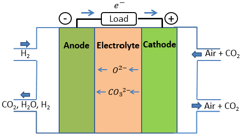 Figure 1 Schematic structure of ceramic-carbonate nanocomposite fuel cell.
Anode reactions:
H2 + O2- → H2O + 2e–
H2 + CO32- → H2O + CO2 + 2e–
Cathode reactions:
½ O2 + CO2 + 2e– → CO32-
½ O2 + 2e– → O2-
Overall cell reaction:
H2 + ½ O2 → H2O
The motivation for this fuel cell technology arises from the fact that the most efficient fuel cell technology i.e. SOFC, operates at high temperatures between 800oC and 1000oC primarily due to limited oxygen ion conductivity in its electrolyte material which consists of yttria-stabilized zirconia (YSZ). This high operating temperature of SOFC causes many degradation issues including chemical and mechanical incompatibilities, permanent microstructural changes and failure of sealing [3,4]. Furthermore, start-up time of SOFC is quite long. Therefore, there is need to replace the YSZ based electrolyte with some alternative electrolyte material which can result in efficient oxygen ion conductivity (higher than 0.1 S/cm) through the electrolyte below 500oC temperature. For this purpose, in low-temperature SOFC the YSZ is replaced with doped ceria i.e. Gadolinium doped cerium oxide (GDC) or Samarium doped cerium oxide (SDC) as electrolyte material. However, still the ionic conductivity for oxygen ion transport is low. There are two main approaches to improve the oxygen ion conduction through GDC or SDC electrolyte. One approach is to dramatically decrease the thickness of the electrolyte layer up to less than ten micrometer thickness [5]. The other approach is to utilize a nanocomposite electrolyte consisting of doped ceria and eutectic mixture of alkali (Na, Li, K) carbonates [6,7,8]. The nanocomposite electrolytes significantly improve the oxygen ion conduction thorough the composite electrolyte even at low temperatures. Depending on the composition of the nanocomposite electrolyte, the operating temperature can be reduced even down to 400oC while keeping high enough ionic conductivity of the electrolyte. Very high conductivity for nanocomposite electrolytes up to 0.4 S per cm has been achieved [9]. Currently, we have been consistently producing nanocomposite electrolytes with impressive over 0.5 S per cm conductivities, which according to our knowledge are the record conductivities for any fuel cell electrolyte [10].
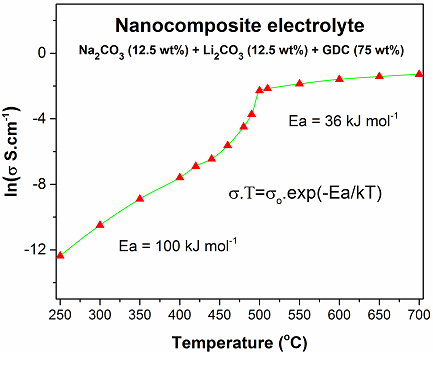 Figure 2 Typical Arrhenius plot of a ceramic-carbonate composite fuel cell. The conductivity is dominated by oxygen ion below eutectic point of alkali carbonate mixture i.e. 500oC in case of Na2CO3 and Li2CO3, and by other ions, most likely carbonate ions, above 500oC.
Conduction mechanisms in CCCFC electrolytes are still under investigation. Apparently, different conduction mechanisms are dominating at different temperatures. For instance, at temperatures below the eutectic point, conduction of oxygen ion through the bulk and interfaces of the SDC or GDC is dominant. However, as the Arrhenius plot in the Figure 2 shows, the conductivity pattern changes dramatically near the eutectic point around 500oC. This sudden change in conductivity implies either conductivity of oxygen ion has greatly increased or conduction of other ions such as carbonate ions, alkali ions, hydrogen or hydroxide ions becomes dominant. There is a higher probability that conduction at higher temperature is dominant by carbonate or alkali ions. However, it is not clear that whether this conduction takes place in bounded or unbounded form of alkali carbonates, since there is a strong ionic bounding between the alkali ions and carbonates. The possible role of hydrogen and hydroxide ions in improving the ionic conductivity of nanocomposite electrolyte needs further investigation. Relative contribution from four parallel channels for ions conduction in a composite electrolyte have been studied, and it was suggested that dominant contribution to the total conductivity of nanocomposite electrolyte originates from transport in the carbonate phase and across the carbonate/oxide interfaces [11]. Figure 3 shows that four parallel conduction paths for ions conduction.
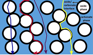 Figure 3 Four different parallel ions conduction paths through oxide phase, oxide/carbonate interfaces, carbonate phase, and both carbonate phase and across oxide/carbonate interfaces.
Though high conductivities can be achieved using nanocomposite electrolytes, there are some aspects which require further attention. For instance, the molten carbonate can corrode the electrode materials. It has been reported that some of the potential electrode materials such as Strontium doped Lanthanum Manganite (LSM) degraded due to Manganese reaction with the aggressive molten carbonates [12]. It has also been reported that lithiated Nickel oxide which is used as cathode material can also dissolve into the molten carbonate [13]. Our high-resolution transmission electron microscopy (HR-TEM) reveals degradation of LSM due to reaction of manganese with the molten carbonates. Furthermore, through XRD studies an interaction between the strontium, which is a common element is most of the potential perovskite-structured cathode materials, including Lanthanum Manganite (LSM), Strontium doped Lanthanum Cobaltite (LSC), Strontium doped Lanthanum Ferrite (LSC), Strontium doped Lanthanum Cobalt Ferrite (LSCF) and Strontium doped Barium Cobalt Ferrite (BSCF), and molten carbonates have been observed to form Strontium carbonate [14]. However, it is not clear how detrimental these interactions are to the overall device performance and stability. In this regard, a comparative stability study using above mentioned perovskite structured electrode materials with nanocomposite electrolytes was conducted at 550oC, and it was found that only cells prepared with LSM cathode materials were degraded and resulted in very high total cell impedance (~300 Ω.cm2). Other cells prepared with LSC, LSF and LSCF showed excellent electrochemical performance resulting in low total cell impedance (~40 Ω.cm2). It was concluded that these three cathode materials are suitable for CCCFCs, at least up to 550oC operating temperature. Furthermore, it was also suggested that in order to study the electrode processes with sufficient reliability, low amplitude of AC signal should be used, otherwise the data would be affected by the non-linearity. Finally, it was shown that total impedance of the cell acquired through electrochemical impedance spectroscopy (EIS) should match with the total impedance obtained through the current-voltage curve. It was noticed that usually 100 mHz – 1 MHz frequency range has been used for EIS studies of the fuel cells, which reveal only part of the electrode processes. Further lowering the frequency of AC signal would give complete picture of the electrode processes. However, the limitation with using lower frequencies for EIS measurements is that it takes very long to complete, that is, 2 to 3 days for a single measurement.
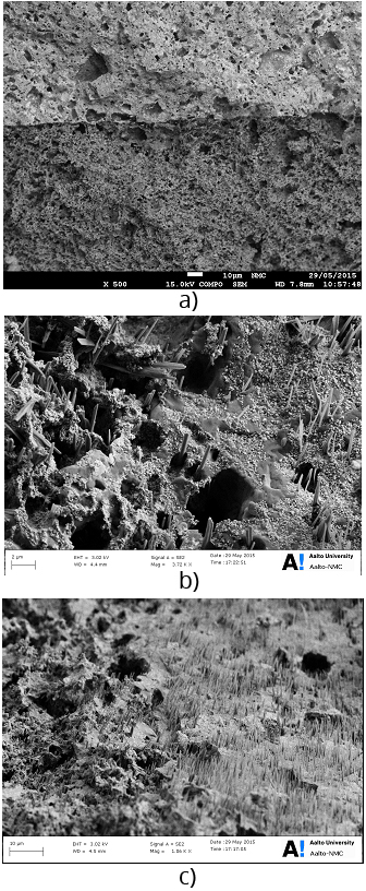 Figure 4 Field emission scanning elctron microscope images of a) nanocomposite electrolyte and electrode interface, b&c) rod-like structures on the nancomposite electolyte and electrode interface either due to formation of alkali hydroxides or merely due to the presence of Li2CO3.
Non-perovskite structured electrode materials such as LiNiCuZn-oxide have been used as efficient electrode materials. Our recent study [7] shows that the synthesis method for the electrode affects its electrochemical properties. It was found in a comparative analysis that LiNiCuZn-electrode prepared with “slurry method” results in lower polarization (0.21 Ωcm2) losses as compared the electrodes prepared with conventional solid method (0.31 Ωcm2). The primary reason for better performance of electrodes prepared with slurry method than conventional solid method, seems to result due to higher surface area (17.7 m2g-1 vs. 1.9 m2g-1) and porosity (7.0 · 10-2 cm3g-1 vs. 6.5 · 10-3 cm3g-1) measured by Brunauer-Emmett-Teller (BET) and Barrett-Joyner-Halenda (BJH) techniques. The scanning electron microscope (SEM) and X-ray diffraction (XRD) measurement results further show that 10 nm – 100 nm particle sizes were obtained with the slurry method. On the other hand, 100 nm – 1 µm particle sizes were produced with the conventional solid method. Therefore, slurry method is clearly better for high performance fuel cells. Nickel oxide which has been used extensively used in MCFC as electrode material. MCFCs utilize alkali carbonates for ionic conduction and operate around 650oC. Dissolution of nickel oxide in molten carbonates has been reported [13] and is one of the major degradation in MCFCs. In CCCFCs the operating temperature is less than 600oC, therefore, nickel oxide might be still an option as electrode material. However, this requires long term stability testing of nickel oxide for CCCFCs.
Generally, a conventional fuel cell consists of three well-defined layers of anode, electrolyte and cathode materials. Recently, ceramic composite fuel cells without distinct electrolyte layer have been reported [15,16,17,18]. Main motivation for these fuel cells was to decrease the manufacturing costs of fuel cells by decreasing the number of material layers without loss in fuel cell performance. Several names have been given to these novel free fuel cells, that is, a single component fuel cell (SCFC), a single layer fuel cell (SLFC), an electrolyte (layer/separator) free fuel cell (EFFC), a non-electrolyte-separator fuel cell (NEFC) and a Schottky junction fuel cell (SJFC). Apparently a cell fuel without an electrolyte should short circuit, however, these fuel cells have been reported up to 1 W per cm2 [17]. Although, different theories based on semiconductor p-n junction, Schottky junction, bulk heterojunction and perovskite solar cells have been given in these studies [15,16,17,18], the working mechanisms of these fuel cells remain unclear since all these studies were merely speculating the working mechanisms without providing any solid experiment or theoretical backing. Therefore, it is recommended to perform a systematic studies to understand the working mechanisms of these kind of fuel cells. The stability of these fuel cells have been investigated much so far.
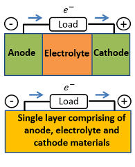 Figure 5 Schematic structure of conventional three layer low-temperature nanocomposite fuel cell and novel single layer low-temperature nanocomposite fuel cell.
The stability of fuel cells is an important aspect for their commercialization. However, there are no standards defined for evaluating their lifetime. There are different accelerating ageing tests commonly used to report the stability of fuel cells. For instance, it is quite common that the stability data is acquired from either potential sweep cycles, thermal cycling or holding the device at high currents/voltages for certain hours. Same is the case for CCCFCs like any other kind of fuel cell technology. The limitation with these commonly used accelerating ageing tests is that they only tell about the degradation in the device performance and not the origin of the degradation reaction. We suggest that the electrochemical methods such impedance spectroscopy, cyclic voltammetry etc. should be coupled with the techniques giving information of the chemical and structural changes in the device leading to the degradation of the performance with the passage of time. Such techniques include Raman spectroscopy, infrared spectroscopy, mass spectroscopy, X-ray photoelectron spectroscopy, XRD, SEM and TEM coupled with energy dispersive X-ray spectroscopy. Another potential method to study degradation in 3-dimentional (3D) is X-ray 3D-tomography. If this technique can be applied for in-situ measurements of the fuel cells, it could reveal details of the processes and related degradation mechanisms.
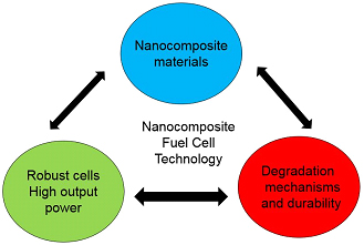 Figure 6 Different paradigm of inter connected research around nanocomposite fuel cells, including development of nanomaterials and their composites, manufacturing of high performance fuel cells and investigating the stability of the devices.
In our current experiments, we have been achieving very high open-circuit voltages (OCV) up to 1.46 V for CCCFCs, when oxygen and carbon-dioxide are fed at the cathode. The OCV drop to 1.2 when only oxygen is fed at the cathode. To our understanding such a high OCV is resulting either from a non-fuel cell reaction (i.e carbon formation) or concentration gradients of the reactant gasses. We are working on understanding the mechanisms. For these cells, we achieved a power density of 500 mW per cm2.
Acknowledgment
We especially thank Academy of Finland for their financial support (Grant No. 282962 and 297204). This work is a part of EU-Indigo project.
References
- The European Parliament and the Council of the European Union, European Commission (2010): Directive 2010/31/EU of the European Parliament and of the Council of 19 May 2010 on the energy performance of buildings (recast). (2010) 13-35.
- Fuel cell market analysis by product (PEMFC, DMFC, PAFC, SOFC, MCFC, AFC) and segment forecasts to 2020. ISBN code: 978-1-68038-087-3, April 2014.
- I. Asghar and P. D. Lund, Catalysis Today 259, 259-265 (2016).
- Patakangas, Y. Ma, Y. Jing, P. Lund, J. Power Sources, 263, 315-331 (2014).
- G. Lee, J. H. Park and Y. G. Shul, Nature Communications, 5, 4045 (2014).
- I. Asghar, S. Lepikko, J. Patakangas, Y. Jing and P. D. Lund, International Journal of Hydrogen Energy, under evaluation, 2015.
- Patakangas, Y. Jing, M. I. Asghar and P. D. Lund, International Journal of Hydrogen Energy, accepted, 2015.
- J. Di, M. Chen, C. Wang, J. Zheng, L. Fan and B. Zhu, J. Power Sources, 195, 4695-4699 (2010).
- Y. Jing, J. Patakangas, P. D. Lund and B. Zhu, International Journal of Hydrogen Energy 38, 16532-16538 (2013).
- M. I. Asghar, I. Khan, S. Basu and P. D. Lund, to be submitted, 2016.
- J. A. Loureiro, S. Rajesh, F. M. L. Figueiredo and F. M. B. Marques, RSC Adv., 4, 59943-59952 (2014).
- R. S. Pereira, S. Rajesh, F. M. L. Figueiredo and F. M. B. Marques, Electrochimica Acta, 90, 71-79 (2014).
- Rajesh, D. A. Maccedo and R. M. Nascimento, A. Mendez-Vilas, Ed. Formatex (2013).
- Rajesh, J. R. S. Pereira, F. M. L. Figueiredo and F. M. B. Marques, Electrochimica Acta, 125, 435-442 (2014).
- Zhu, H. Qin, R. Raza, Q. Liu, L. Fan, J. Patakangas and P. Lund, International Journal of Hydrogen Energy 36, 8536-8541, 2011.
- Zhu, P. Lund, R. Raza, J. Patakangas, Q. A. Huang, L. Fan and M. Singh, International Journal of Hydrogen Energy 2, 1179-1185, 2013.
- Zhu, P. Lund, R. Raza, Y. Ma, L. Fan, M. Afzal, J. Patakangas, Y. He, Y. Zhao, W. Tan, Q. A. Huang, J. Zhang and H. Wang, Advanced Energy Materials 5, 1401895, 2015.
- Zhu, Y. Huang, L. Fan, Y. Ma, B. Wang, C. Xia, M. Afzal, B. Zhang, W. Dong, H. Wang and P. D. Lund, Nano Energy, accepted 2015.

Meet Our Editors

Advert Logos