
Time Manipulation of Magnetic and Metallic Nanoparticles for Enhanced Imaging
Zeev Zalevsky
Faculty of Engineering and the Nanotechnology Center, Bar Ilan University, Ramat-Gan, 52900, Israel
Introduction
Currently the usage of nanoparticles (NP) is significantly increasing while integrating them into various fields of research and technology involving medical treatment as e.g. for drug delivery [1-5] or for ablation and photo thermal therapy [6-11], or for sensing and imaging [12,13]. In this short review paper I present the research activity done in my lab and which is oriented especially towards the directions of enhanced and super resolved imaging based time manipulation of different types of NPs.
Usage of nanoparticles for molecular imaging of internal tissues
When different types of metallic or magnetic NPs that are labeled to target different types of cells, are inserted into a tissue, they can be externally manipulated and thus assist us to externally image the internal tissues containing the targeted cells [14]. For instance, the molecular like imaging can be obtained by externally illuminating the tissue with a laser having wavelength that is matched to the plasmonic resonance of the different types of the NPs that are in use. The externally applied field causes the different types of NPs to move in time in a different way as they have different mechanical properties and thus if one externally observes the dynamics of the secondary speckle patterns scattered from the different types of tissues (targeted by different types of NPs), significant differentiation may be observed [14]. Thus, since each group of NPs produces different temporal dynamics, it allows us to image the different types of cells that were targeted by the different groups of the NPs despite the fact that we collect only highly scattered light.This can be done with magnetic NPs manipulated by external alternating magnetic field [14] as well as with charged metallic NPs being manipulated by external alternating electrical field [15].
As an example one may see the results presented in Fig. 1(a) and 1(b) where we compared the displacement of 50 nm, 100 nm and 200 nm magnetic NPs under magnetic field (green, red and blue lines respectively). In Fig. 1(b) one can see that the increase in magnetic NP diameter decreases the frequency of the temporal displacement peak, while at the same time, increasing the displacement amplitude [16]. For example the two peaks obtained for 200 nm and 100 nm magnetic NPs are differentiated by 30% in amplitude (-2.8dB and -4.0dB respectively) and have a temporal frequency shift of 6%, while 200 nm and 50 nm magnetic NPs are differentiated by 60% (-2.8dB and -6.8dB respectively) and have a temporal frequency shift of 30%. This indicates the possibility of distinguishing between particles having different sizes in vivo, by using secondary speckle analysis approach [14].
In Fig. 1(c) we present how application of external alternating external electric field gives rise to dramatic modulation of the scattered light (secondary speckle patterns analysis). For this experiment we used Au nanorod embedded in sol-gel matrix [15]. On may observe the generation of higher-order harmonics upon Fourier transformation of the speckle beats. The distinct colors in Fig. 1(c) correspond to different pixels in the pulse area (e.g. analysis of different speckles in the region of interest), demonstrating the universal nature of this phenomenon (being not space dependent). The observation of higher harmonics for the beats of the speckle patterns is ascribed to the sinusoidal dependence of nanorod motion within the constrained sol-gel environment, according to the Ther model [15, 17-19].
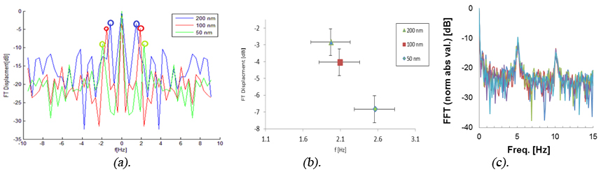 Fig.1 (a)., (b). Experimental demonstration of the influence of magnetic NPs size on (a).The displacement spectrum (b).The average amplitude of displacement of the spectral peak of magnetic NPs. The experiments were done at concentration of 10 mg/ml and at 1Hz with different Amine coated magnetic NPs sizes of: 200 (blue), 100 (red) and 50 (green) nm. (c). Electrical manipulation of nanorods embedded in sol-gel matrix: High-order harmonics observed through Fourier transform of the temporal fluctuations of the speckle pattern.
Nanoparticles based nanoscopy
Usage of metallic NP in order to realize localization based (non-fluorescent) nanoscopy has been demonstrated before in Ref. [20]. The operation principle was to use sub wavelength NPs moving in random Brownian motion in proximity of the inspected object such that their density is sufficiently low and thus the blurring point spread function (PSF) of the imager is smaller than the average separation distance between two adjacent moving NPs. Thus, by using localization algorithms, the center of each blurred moving PSF (corresponds to a specific NP) can be localized in precision being much higher than the imaging resolution which is the size of the PSF. Since each NP passing in proximity of a given spatial feature of the examined object generates a down conversion of the high spatial frequencies into low spectral band (spatial frequencies spectrum), a set of such time changing images (time multiplexing) can allow realization of a super resolved image with resolution equivalent to the localization resolution at which the position of the NPs is estimated (because the spatial pattern with the estimated positions of the NPs is used as the decoding pattern to perform the super resolved reconstruction) [21-25]. The time multiplexing, i.e. the need to capture several time changing images with different positions of the NPs is needed in order to fully cover (sample) the field of regard and in order to be able to properly decode the encoded sub wavelength resolution information.
The problem is that the localization precision which sets the final super resolution limit highly depends on the signal to noise ratio (SNR) of the captured time changing set of images. In order to increase the SNR and therefore the resulted resolution we proposed to use the lock-in-amplification concept [26-28]. The idea is as follows: We use different types of NPs while each type has a different plasmonic resonance (i.e. the scattering peak is obtained at different wavelengths). Then, we are illuminating the sample with several lasers at different wavelengths while each wavelength is matched to the different types of the NPs and each laser is blinking at different temporal frequency. The lock-in-amplification effect is realized due to the fact that each type of NPs blinks at different temporal frequency and thus they can be observed at higher SNR (as the NPs blink at specific a priori known temporal frequency while the noise is spread over the entire temporal spectrum) but also since different types of NPs are used and each blinks at different temporal frequency then sub PSF localization can also be obtained if several NPs from different types are positioned from each other at distance smaller than the size of the PSF (and can be differentiated from each other only due to their different blinking frequency).
In the experimental results aiming to demonstrate this super resolving concept, samples of human epidermoid carcinoma cell line, A431, were injected with 20nm spheres gold NPs (GNPs) with absorption and scattering peak at 532nm and 15nm x 50nm rods GNPs with absorption and scattering peaks at 532nm and 785nm immobilized on a coverslip, using a known protocol [26]. The GNPs were not targeted into a specific area within a cell and therefore they are randomly distributed inside the cells. In order to visualize the effect of different types of GNPs on the scattering of the cells, 4 different samples were imaged using a dark-field microscope (Nikon i50). The first sample was a control set with cells only (left part, Fig. 2(a)). The second sample was cells tagged with spherical GNPs. Due to their scattering peak they make the cell appear green (left part, Fig. 2(b)). The third sample was cells tagged with rods GNPs. Here, due to their dominant scattering peak they make the cell appear red (left part, Fig. 2(c)).The last sample was of cells that were tagged with both spherical and rods GNPs. Therefore, the cells appear to contain both green and red colors (left part, Fig. 2(d)).
The proposed method was then tested using the experimental setup in which a function generator (AFG3022B by Tektronix) was used to create two square waves with known frequencies ofν01=13Hz and ν02=25Hz (that fulfil the Nyquist sampling criteria as the frame rate of the camera was 215 frames/s) and a duty cycle of 50%. The first signal at ν01 was connected to the modulation port of a green laser at 532nm (Photop DPGL-2100F) and the second signal at ν02 was connected to the modulation port of a red laser at 785nm (Oxxius LBX-785S). The modulated beams illuminated the sample and the scattered light as a function of time was recorded using a CMOS camera(PixeLink PL-A741-E). The images were taken with such parameters that their SNR was calculated to be -27dB. A bright field image of the sample at a size of 750X650 pixels was taken with the Olympus BX51 microscope using X40 objective lens (right part, Fig. 2(a)). The proposed temporal flickering technique was applied to the sequence of recorded images first with the frequency ν01, followed with the same processing at ν02. Since the rods GNPs also have a minor scattering peak at 532nm, the same as that of the spheres, the processed image with ν01 contained both the spherical and the rods GNPs. Therefore, the processed image with ν02, that contained only the rods GNPs, was subtracted from the ν01 image and the result was two images, one for each type of GNP. The final image that represents the two types of GNPs in the sample is the sum of the two images, where for visualization purposes each type was colored differently, in green and red (right part, Fig. 2(b)). The right part, Fig. 2(c) is the superimposing of Fig. 2(a) and 2(b) (right part). The overlap between the locations of the GNPs to that of the cells, indicates that the GNPs are concentrated inside the cells. In order to validate the ability of the method to detect overlapping GNPs, a reference image of the sample was taken using continuous illumination with the two lasers at high power of 50mW. The obtained image was of all the GNPs in the sample, where areas of overlapping GNPs appear as larger spots. Right part, Fig. 2(d) is a zoom-in on a 40×50 pixels area inside the sample that contains three spots. The same area with the proposed method is presented in the right part, Fig. 2(e), where each of the spots contains two different types of GNPs.
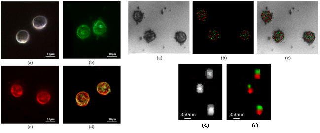 Fig. 2 Left: Dark field image of 4 different samples. (a). Cells only. (b). Cells tagged with spherical GNPs. (c). Cells tagged with rods GNPs. (d). Cells tagged with both spherical and rods GNPs. Right: Expeirmentally extracted images. (a). A bright field image of the sample. (b).The reconstructed image of the sample using the proposed time flickering approach for each of the two frequencies (marked in green and red). (c).The superimposing of (a) and (b). (d). Zoom-in on an area inside the sample that contains three spots. The image was captured under conditions of continuous illumination of the sample with the two lasers at high power of 50mW. (e).The same area with the proposed method, where each of the spots contains two different types of GNPs.
Acknowledgements
The results overviewed in this paper are based upon the research work done together with A. Vegerhof, A. Rudinzky, Y. Beiderman, H. Duadi, R. Popovtzer, M. Ritenberg, E. Beilis, A. Ilovitsh, Z. Barkai, A. Shahmoon, S. Richter, R. Jelinek, T. Ilovitsh, Y. Danan, R. Meir and A. Meiri.
References
- Koneracka, P. Kopčanský, “Direct binding procedure of proteins and enzymes to fine magnetic particles,” Journal of Magnetism and Magnetic Materials 252, 409-411(2002).
- Veiseh, J.W. M. Zhang, “Design and fabrication of magnetic nanoparticles for targeted drug delivery and imaging,” Advanced drug delivery reviews 62(3), 284–304 (2010).
- Widder, “Magnetic microspheres: a model system for site specific drug delivery in vivo,” Proceedings of the Society for experimental biology and medicine 58, 141–146 (1978).
- Dobson, “Magnetic nanoparticles for drug delivery,”Drug Development Research 67, 55–60 (2006).
- Berry, A. Curtis, “Functionalization of magnetic nanoparticles for applications in biomedicine,” Journal of physics D: Applied physics 36, 198-206 (2003).
- S. Kalambur, B. Han, B.E. Hammer, T.W. Shield, J.C. Bischof, “In vitro characterization of movement, heating and visualization of magnetic nanoparticles for biomedical applications,” Nanotechnology 16(8), 1221–1233 (2005).
- Huang X, M. A. El-Sayed, “Plasmonic photo-thermal therapy (PPTT),” Alexandria J. Med. 47(1), 1–9 (2011).
- Richter, M. Kettering, F. Wiekhorst, U. Steinhoff, I. Hilger, L. Trahms, “Magnetorelaxometry for localization and quantification of magnetic nanoparticles for thermal ablation studies,” Phys. Med. Biol. 55(3), 623–633 (2010).
- Jaque, L. Martínez Maestro, B. del Rosal, P. Haro-Gonzalez, A. Benayas, J. L. Plaza, E. Martín Rodrígueza and J. García Solé, “Nanoparticles for photothermal therapies,” Nanoscale. 6, 9494–9530 (2014).
- P. O’Neal, L. R. Hirsch, N. J. Halas, J. D. Payne, J. L. West, “Photo-thermal tumor ablation in mice using near infrared-absorbing nanoparticles,” Cancer Lett. 209(2), 171–176 (2004).
- Cardinal, J. R. Klune, E. Chory, et al.” Noninvasive radiofrequency ablation of cancer targeted by gold nanoparticles,” Surgery 144(2), 125–132 (2008).
- Jain, J. Richey, M. Strand, “Magnetic nanoparticles with dual functional properties: drug delivery and magnetic resonance imaging,” Biomaterials. 29, 4012–4021 (2008).
- Huang, I. H. El-Sayed, W. Qian, M. A. El-Sayed,“Cancer cells assemble and align gold nanorods conjugated to antibodies to produce highly enhanced, sharp, and polarized surface Raman spectra: a potential cancer diagnostic marker,” Nano Lett. 7(6), 1591–7 (2007).
- Vegerhof, A. Rudinzky, Y. Beiderman, H. Duadi, R. Popovtzer and Z. Zalevsky, “Manipulated magnetic nano particles for Photonic biomedical mapping,” Nanoscience and Nanotechnology Letters (accepted).
- Ritenberg, E. Beilis, A. Ilovitsh, Z. Barkai, A. Shahmoon, S. Richter, Z. Zalevsky and R. Jelinek, “Beating speckles” via electrically-induced vibrations of Au nanorods embedded in sol-gel,” Sci. Rep. 4, Nature Publishing Group, Article 3666 (2014).
- Pankhurst and J. Connolly, “Applications of magnetic nanoparticles in biomedicine,” Journal of physics D: Applied physics. 36, 167–181 (2003).
- A. Barnes, “Thixotropy- a review,” J. Non-Newtonian Fluid Mech. 70, 1–33 (1997).
- Coussot, Q. Nguyen, H. Huynh, and D. Bonn, “Avalanche behavior in yield stress fluids,” Phys. Rev. Lett. 88, 1–4 (2002).
- Roussel, “A thixotropy model for fresh fluid concretes: Theory, validation and applications,” Cem. Concr. Res. 36, 1797–1806 (2006).
- Gur, D. Fixler, V. Micó, J. Garcia and Z. Zalevsky, “Linear optics based nanoscopy,” Opt. Exp. 18, 22222-22231 (2010).
- Zalevsky and D. Mendlovic Optical Super Resolution, Springer (2004).
- Zalevsky D. Mendlovic and A. W. Lohmann, Progress in optics, Vol. XL, Ch. 4: “Optical system with improved resolving power,” (1999).
- Mendlovic, A. W. Lohmann, N. Konforti, I. Kiryuschev and Z. Zalevsky, “One dimensional superresolution optical system for temporally restricted objects,” Appl. Opt. 36, 2353-2359 (1997).
- Mendlovic, I. Kiryuschev, Z. Zalevsky, A. W. Lohmann and D. Farkas, “Two dimensional super resolution optical system for temporally restricted objects,” Appl. Opt. 36, 6687-6691 (1997).
- Shemer, Z. Zalevsky, D. Mendlovic, N. Konforti and E. Marom, “Time multiplexing super resolution based on interference grating projection,” Appl. Opt. 41, 7397-7404 (2002).
- Ilovitsh, Y. Danan , R. Meir, A. Meiri and Z. Zalevsky, “Cellular imaging using temporally flickering nanoparticle,” Sci. Rep. 5, Nature Publishing Group, Artcile 8244 (2014).
- Ilovitsh, Y. Danan, A. Ilovitsh, A. Meiri, R. Meir and Z. Zalevsky, “Superresolved labeling nanoscopy based on temporally flickering nanoparticles and the K-factor image deshadowing,” Biomedical Opt. Exp. 6, 1262-1272 (2015).
- Ilovitsh, Y. Danan, R. Meir, A. Meiri and Z. Zalevsky, “Cellular superresolved imaging of multiple markers using temporally flickering nanoparticles,” Sci. Rep., Nature Publishing Group 5, Article number: 10965 (2015).

Meet Our Editors

Advert Logos